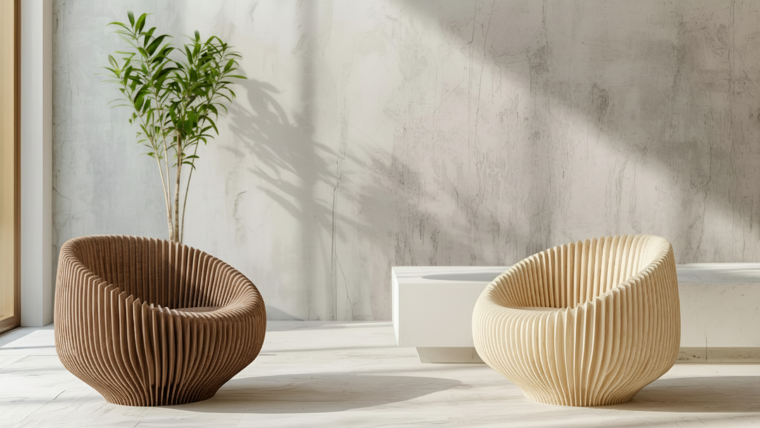


Designing Parts for Thermoplastic Pellet‑Based Large Format Additive Manufacturing (LFAM)

Photo from Aibuild
Pellet-based LFAM changes how you think about geometry and process. A screw-driven melt system and tunable nozzle orifices deposit wide, tall beads at industrial throughputs—fewer layers and faster builds—along with new constraints around bead geometry, heat management, overhangs, and post-processing. This guide distills shop-proven DFAM (design for additive manufacturing) principles specifically for thermoplastic pellet-based LFAM, with examples and tips aligned to Massive Dimension hardware and accessories.
Key Takeaways
- Design to the bead. Make walls, radii, and features intentional multiples of bead width (BW) and layer height (LH) to avoid gaps, overfill, and weak seams.
- Control heat and support yourself. Respect overhang limits (~45°) and plan layer times so beads fuse without sagging or delaminating; prefer ribs and smart orientation over supports.
- Print near-net; finish precisely. Oversize critical faces and corners, then machine to final tolerance. Dry pellets and use a heated, level bed to reduce warp and variability.
- Think “LFAM DFAM.” Consolidate parts where it reduces assembly, design ribs/webs instead of dense infill, and choose orientations that shorten cycle time while protecting functional faces.
Pellet-Based LFAM vs. Filament FFF—What Actually Changes
Pellet systems melt and meter granulate with a screw extruder, enabling much higher output and larger, more stable beads than small-format filament printers. Nozzle orifices can be far larger than desktop norms, and material changeovers require purge time—so plan single-material builds and continuous toolpaths whenever possible. Compared to filament FFF (fused filament fabrication), pellet LFAM prioritizes throughput and bead stability.
Drying is mandatory: moisture causes foaming, poor surface finish, and weak inter-bead fusion. (See drying and bed notes below.)
Massive Dimension tie-in
-
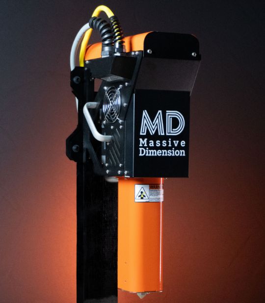
MDPH2: Compact, proven pellet head. ~2 lb/hr output (material/test dependent), up to 450 °C. Great for getting into LFAM and for finer nozzles; broad material flexibility including ABS, PLA, HIPS, PC, and elastomers.
👉 Explore MDPH2 -
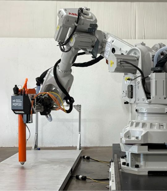
MDPE10: Higher-throughput head with 4 heat zones and ~10 lb/hr capability (material-dependent), designed for stable melt at speed and shorter cycles on large parts. Includes a longer L/D (length-to-diameter) ratio screw for stable melt at flow.
👉 Explore MDPE10
Know Your Extruder & Nozzle (Massive Dimension Options)
Your nozzle sets your effective “pixel size.”
-
Standard MD nozzles ship at 1.5 mm and can be drilled larger for higher throughput.
👉 MD Nozzles -
Higher-resolution path: The MD E3D adapter is documented on the MD Nozzles page and accepts Volcano 0.4–1.2 mm nozzles for smaller features and smoother finishes.
👉 E3D Volcano Adapter (see Nozzles page) - Pro tip: Match nozzle size to extruder throughput so beads stay stable; over-feeding a small orifice compromises control and finish.
-
Access option: The MD Extended Length Nozzle improves reach into deep features without sacrificing bead stability.
👉 Extended Length Nozzle
Bead-First Modeling: Practical Rules
- Even-multiple walls: Favor 2×, 4×, 6× BW to minimize seam starts/stops and internal voids.
-
Representative patterns (shop-proven):
– 0.3 in (≈7.6 mm) nozzle → ≈0.34 in BW, ≈0.15 in LH
– 0.4 in nozzle → ≈0.50 in BW, ≈0.20 in LH
Treat these as scalable patterns; validate with your slicer and a short process trial. - Holes & thin webs: Avoid knife-edge single-bead features. Print solid where possible and post-machine holes/slots.
- Quick bead math: Targeting ~10 mm BW? Make a 40 mm wall four beads wide; pick LH ≈ 0.35–0.5× BW (often near ~½ of the effective nozzle diameter that forms that bead).
Overhangs, Bridges & Self-Supporting Strategies
- Overhang limit: Keep local overhangs ≤ ~45° from horizontal. Use fillets/lofts to maintain support, or split/re-orient geometry.
- Bridging: Keep spans short. At LFAM bead sizes, thermal mass limits bridge performance—close large openings and CNC the cutout afterward.
- Skip bulky supports: Ribs, angled faces, and orientation beat supports for speed, material use, and part quality—especially at large bead sizes.
Layer Time, Heat & Path Planning
- Stay in the fusion window: The previous layer must be hot enough to fuse and cool enough to carry the next.
- Balance layer times: Slow slightly or print multiple parts per layer to keep bonding consistent across geometries.
- Favor continuity: Continuous toolpaths reduce non-printing moves and heat imbalance.
- Process stability: The MDPE10’s four zones stabilize melt temperature at higher throughputs.
Print Near-Net, Then Machine for Precision
LFAM excels when you print for structure, machine for tolerance.
- Allowances that work: Oversize critical faces by ~0.3–0.6× BW (XY) and ~0.3–0.6× LH (Z) so finishing cuts land near bead mid-thickness.
- Corners & edges: Expect to machine sharp corners for crisp edges.
- Orientation for finish: Stand critical faces vertically to reduce staircase, then CNC to hit sealing or Class-A surfaces.
Material Selection, Drying & Build Surface
- Materials: ABS (acrylonitrile butadiene styrene), PLA (polylactic acid), HIPS (high-impact polystyrene), PETG (polyethylene terephthalate glycol), and fiber-filled variants are common across MDPH2 and MDPE10. PC (polycarbonate) and elastomers TPU/TPE (thermoplastic polyurethane / thermoplastic elastomer) run on MDPH2; elastomer use on MDPE10 is material-profile dependent. Fiber fill lowers CTE (coefficient of thermal expansion)/shrinkage for better dimensional stability.
-
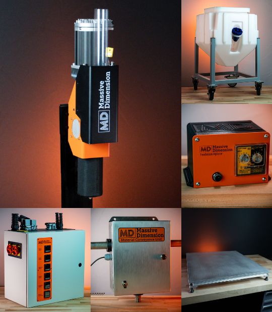
Drying: Use an in-line dryer targeting ultra-low dew points to keep beads dense and fusion strong.
👉 MD Pellet Drying System -
Build surface: A heated, flat, level modular bed (up to ~130 °C depending on model) improves first-layer reliability and reduces warp. Let parts cool on the bed before removal.
👉 XL Heated Build Surface (1000 × 1600 mm)
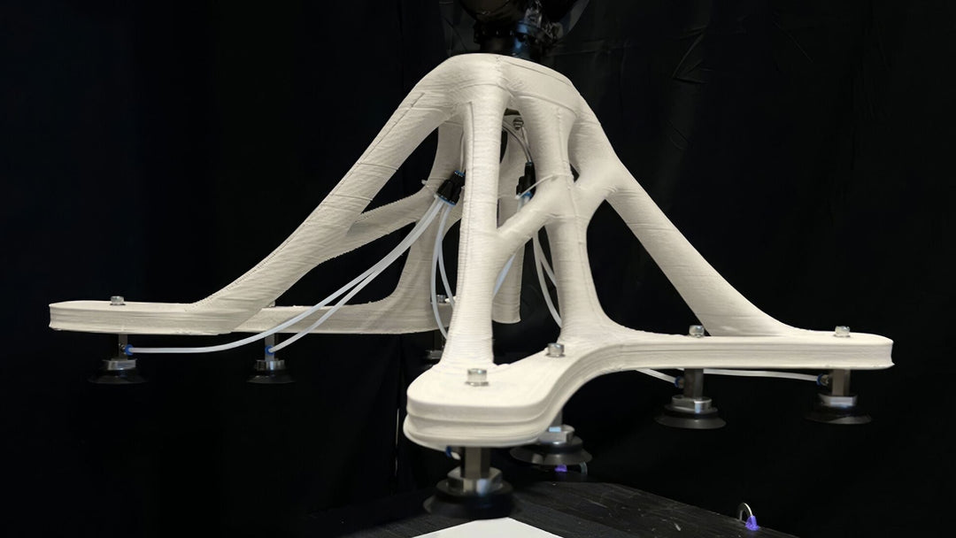
Lightweighting that Works at LFAM Scale
Traditional “% infill” doesn’t translate well to LFAM. Use hollow shells with integrated ribs/webs/spars to carry load with less material and shorter cycles. Size ribs as bead-multiples and leave machining access for post-ops. Part consolidation—combining multiple components into a single LFAM print—can also eliminate joinery and cut assembly time when it serves function and serviceability.
Orientation & Build Strategy (DFAM Lens)
Choose orientations that:
- keep functional faces clean (or vertical for best finish),
- minimize support-like features (ribs/angles over sacrificial support), and
- shorten cycle time (fewer retractions, longer continuous paths).
These orientation tradeoffs help you reach reliable throughput without compromising the faces you care about most.
CAD Tactics That Pay Off
- Lock a bead grid early: Define BW and LH; derive wall/rib thickness, fillet radii (≥1–2× BW), and boss diameters from that grid.
- Hide seams: Park bead starts/stops on less-critical faces or along internal ribs.
- Design for drilling/tapping: Print solid pads; add threads post-print.
- Parametric thinking: Use parameters for bead-multiples so you can scale or transfer builds across cells quickly.
Estimating Build Time with Massive Dimension Throughput
Build time ≈ part mass ÷ extruder mass-throughput
- Example: A 25 lb PLA tool on MDPE10 at ~12.7 lb/h ≈ ~2 hours of extrusion (plus motion/pauses and start/stop routines).
- MDPH2 at ~2 lb/h suits smaller parts or higher-resolution nozzles.
Always validate with your slicer and process plan.
FAQ
Smallest reliable feature?
Plan 1–2× BW as your minimum credible feature. For small details, use the MD E3D adapter (see MD Nozzles page) with 0.4–1.2 mm Volcano nozzles—or print solid and machine.
👉 Adapter on MD Nozzles page: View Nozzles & Adapter
Do I need supports?
Usually not. Design for ≤45° overhangs, add ribs/buttresses, or split/re-orient the part. Supports at LFAM scale add time, cost, and removal risk.
How do I minimize warp and splits?
Dry pellets, use a heated build surface, keep layer times in the bonding window, consider fiber-filled materials, and let parts cool on the bed before removal.
👉 Dryer: Pellet Drying System • Heated Bed: XL Heated Build Surface
MDPH2 vs. MDPE10?
MDPH2 (~2 lb/h): lighter setups, finer nozzles, broad material flexibility (incl. elastomers).
👉 Shop MDPH2
MDPE10 (~10–12.7 lb/h): large parts, shorter cycles, four heat zones and a longer L/D screw for stable melt at high flow.
👉 Shop MDPE10
What about infill?
Most LFAM parts are shell-and-rib designs—faster, lighter, and easier to machine than dense infill.
Bonus: Complete Systems
If you want the entire LFAM workflow out of the box, explore our turnkey cells:
-
MDAC Industrial Series — Large envelopes, guarding, track options, and integrated post-processing paths.
👉 Explore MDAC Industrial -
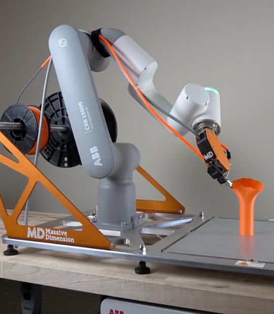
MDAC Cobot Series — Compact cells built for research, prototyping, and agile production.
👉 Explore MDAC Cobot
Pellet-based LFAM rewards teams that think in beads, heat, and toolpaths. When you lock BW/LH early, keep overhangs realistic, balance layer times, and plan for near-net machining, you get repeatable quality at industrial speed. Pair those DFAM habits with the right extruder/nozzle strategy, robust drying, and a stable heated bed, and you’ll deliver stronger parts, cleaner finishes, and shorter lead times.
Whether you’re prototyping large components, tooling for production, or standing up a turnkey cell, our team can help you dial in materials, bead geometry, and process parameters for your application.
Ready to see what LFAM can do for you?
Book a Discovery Call